- 您现在的位置:买卖IC网 > Sheet目录362799 > EVAL-AD1936EB (Analog Devices, Inc.) 4 ADC/8 DAC with PLL, 192 kHz, 24 Bit CODEC
AD1935/AD1936/AD1937/AD1938/AD1939
Preliminary Technical Data
Serial Data Ports—Data Format
Rev. Pr
I
| Page 12 of 30
The eight DAC channels output or accept a common serial bit clock
and left-right framing clock to clock in the serial data. The four
ADC channels output or accept a common serial bit clock and left-
right framing clock to clock out the data. The clock signals are all
synchronous with the sample rate. In the AUX Modes, set in ADC
Control 1 and DAC Control 0, the DACs use the ADC serial bit
clock and left-right clock as the DAC clock pins are used for the
auxiliary ADC/DAC serial clocks.
The ADC and DAC serial data modes default to I
2
S. The ports can
also be programmed for left-justified, right-justified and TDM
modes. The word width is 24 bits by default and can be
programmed for 16 or 20 bits. The normal TDM mode can be
daisy-chained with a second AD193X and will support 16 channels
at 48 kHz, 8 channels at 96 kHz or 4 channels at 192 kHz. There is
also a dual-line TDM mode to support 8 channels at 192 kHz.
The special auxiliary modes are provided to allow two external
stereo ADCs and/or two external stereo DACs to be interfaced with
the AD193X to provide up to 8 in/12 out operation or 2 AD193Xs
to be chained for up to 16 in/16 out operation. These modes
provide a glueless interface to a single SHARC serial port, allowing
the DSP to access up to 16 channels of analog I/O. In these modes
many pins are redefined, see table 10. See Figure 18 for details of
these modes.
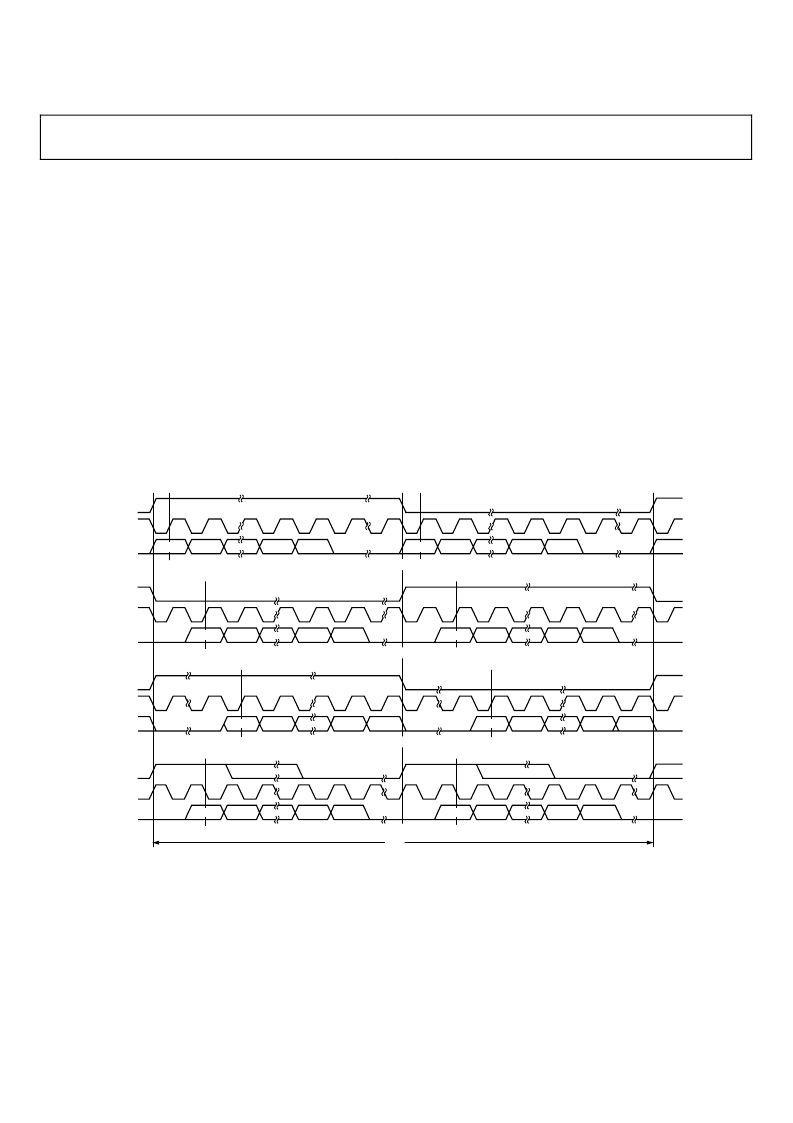
The following figures show the serial mode formats.
LRCLK
BCLK
SDATA
LRCLK
BCLK
SDATA
LRCLK
BCLK
SDATA
LRCLK
BCLK
SDATA
LEFT CHANNEL
RIGHT CHANNEL
LEFT CHANNEL
RIGHT CHANNEL
MSB
LSB
LSB
LSB
LSB
LSB
LEFT JUSTIFIED MODE––16 BITS TO 24 BITS PER CHANNEL
I
2
S MODE––16 BITS TO 24 BITS PER CHANNEL
RIGHT JUSTIFIED MODE––SELECT NUMBER OF BITS PER CHANNEL
DSP MODE––16 BITS TO 24 BITS PER CHANNEL
NOTES
1. DSP MODE DOES NOT IDENTIFY CHANNEL
2. LRCLK NORMALLY OPERATES AT f
S
EXCEPT FOR DSP MODE WHICH IS 2
×
f
3. BCLK FREQUENCY IS NORMALLY 64
×
LRCLK BUT MAY BE OPERATED IN BURST MODE
MSB
MSB
MSB
LSB
LEFT CHANNEL
MSB
LSB
MSB
RIGHT CHANNEL
LSB
MSB
MSB
1/f
S
Figure 13. Stereo Serial Modes
发布紧急采购,3分钟左右您将得到回复。
相关PDF资料
EVAL-AD1937EB
4 ADC/8 DAC with PLL, 192 kHz, 24 Bit CODEC
Eval-AD1940EB
SigmaDSP-TM Multichannel 28-Bit Audio Processor
EVAL-AD1953EB
16-bit fixed point DSP with Flash
EVAL-AD1958EB
PLL/Multibit DAC
EVAL-AD1959EB
PLL/Multibit DAC
EVAL-AD1974EB
4 ADC with PLL, 192 kHz, 24-Bit Codec
EVAl-AD1974EBZ
4 ADC with PLL, 192 kHz, 24-Bit Codec
EVAL-AD1990EB
Audio Switching Amplifier
相关代理商/技术参数
EVAL-AD1937AZ
功能描述:BOARD EVAL FOR AD1937 RoHS:是 类别:编程器,开发系统 >> 评估演示板和套件 系列:- 标准包装:1 系列:PSoC® 主要目的:电源管理,热管理 嵌入式:- 已用 IC / 零件:- 主要属性:- 次要属性:- 已供物品:板,CD,电源
EVAL-AD1937EB
制造商:AD 制造商全称:Analog Devices 功能描述:4 ADC/8 DAC with PLL, 192 kHz, 24 Bit CODEC
EVAL-AD1937EBZ
制造商:Analog Devices 功能描述:EB SINGLE CHIP CODEC 4 ADC'S W/DIFF OUTP - Boxed Product (Development Kits)
EVAL-AD1938AZ
功能描述:BOARD EVAL FOR AD1938 RoHS:是 类别:编程器,开发系统 >> 评估演示板和套件 系列:- 标准包装:1 系列:PSoC® 主要目的:电源管理,热管理 嵌入式:- 已用 IC / 零件:- 主要属性:- 次要属性:- 已供物品:板,CD,电源
EVAL-AD1938EB
制造商:AD 制造商全称:Analog Devices 功能描述:4 ADC/8 DAC with PLL, 192 kHz, 24-Bit CODEC
EVAL-AD1938EBZ
制造商:Analog Devices 功能描述:EVAL BD FOR MULTI CHANNEL 96KHZ CODEC - Boxed Product (Development Kits)
EVAL-AD1939AZ
功能描述:BOARD EVAL FOR AD1939 RoHS:是 类别:编程器,开发系统 >> 评估演示板和套件 系列:- 标准包装:1 系列:PCI Express® (PCIe) 主要目的:接口,收发器,PCI Express 嵌入式:- 已用 IC / 零件:DS80PCI800 主要属性:- 次要属性:- 已供物品:板
EVAL-AD1939EB
制造商:Analog Devices 功能描述:EVAL - Bulk